

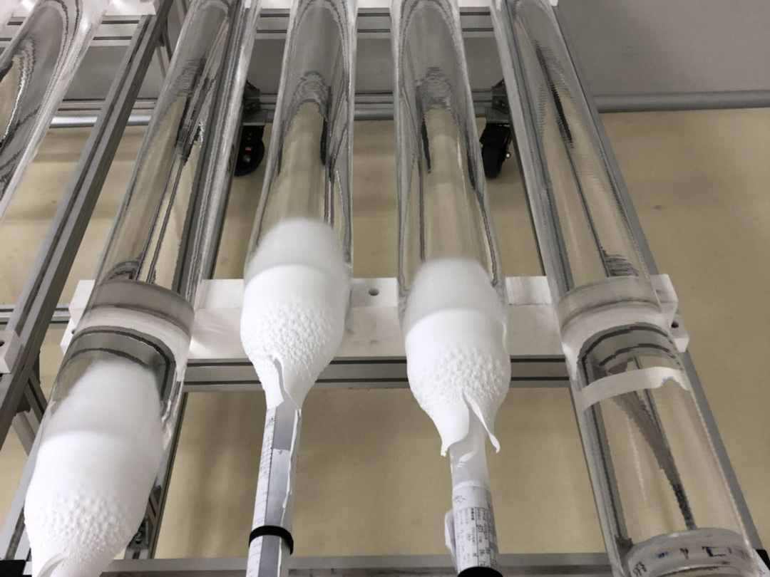
ORIC process:150mm G.657.A2 Optial Fiber Preform
Preform Specifications
Preform Dimensions
The preform dimensions shall be as in the Table 1.1 below.
Table 1.1 Preform Dimensions
| Item | Requirements | Remark | |
| 1 | Average Preform Diameter (O.D.) | 135 ~ 160 mm | (Note 1.1) |
| 2 | Maximum Preform Diameter (ODmax) | ≤ 160 mm | |
| 3 | Minimum Preform Diameter (ODmin) | ≥ 130 mm | |
| 4 | Tolerance of O.D. (within a Preform) | ≤ 20 mm ( in straight part ) | |
| 5 | Preform Length (including handle part) | 2600 ~ 3600 mm | (Note 1.2) |
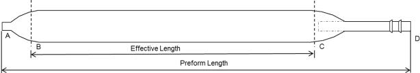
| 6 | Effective length | ≥ 1800 mm | |
| 7 | Taper length | ≤ 250 mm | |
| 8 | Diameter at the end of taper | ≤ 30 | |
| 9 | Preform Non-circularity | ≤ 1 % | |
| 10 | Concentricity Error | ≤ 0.5 μm | |
| 11 | Appearance | (Note 1.4&1.5) |
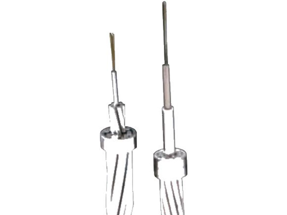
Figure 1.1 Shape of a Preform
Note 1.4: The bubbles in the outer cladding region (see Figure 1.2) shall be permitted, depending on the size; the number of bubbles per unit volume shall not exceed these stipulated in the Table 1.2 below.
Table 1.2 Bubble in a Preform
Location and Size of Bubble |
Number / 1,000 cm3 |
|
Core Region (=core + inner cladding) |
(See Note 1.5) |
|
|
Outer Cladding Region (=interface + outer cladding) |
~ 0.5 mm |
No Count |
0.5 ~ 1.0 mm |
≤ 10 |
|
1.0 ~ 1.5 mm |
≤ 2 |
|
1.5 ~ 2.0 mm |
≤ 1.0 |
|
2.1 mm ~ |
(See Note 1.5) |
|
Figure 1.2 Cross-sectional View of a Preform
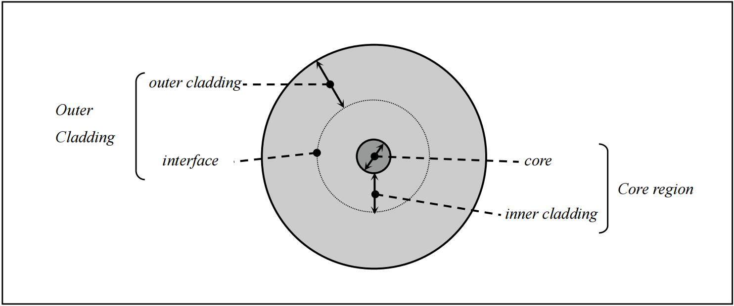
Figure 1.2 Cross-sectional View of a Preform
Chargeable Weight
Target Fiber Characteristics
When the drawing conditions and the measurement conditions are optimum and stable, the preforms shall be expected to meet the target fiber specifications as shown in Table 2.1.
Table 2.1 Target Fiber Characteristics
Item |
Requirements |
|
|
1 |
Attenuation at 1310 nm |
≤ 0.34 dB/km |
|
Attenuation at 1383 nm |
≤ 0.34 dB/km |
(Note 2.1) |
|
Attenuation at 1550 nm |
≤ 0.20 dB/km |
|
|
Attenuation at 1625 nm |
≤ 0.23 dB/km |
|
|
Uniformity of Attenuation |
≤ 0.05 dB/km at 1310&1550 nm |
|
|
2 |
Mode Field Diameter at 1310 nm |
9.1± 0.4 µm |
|
3 |
Cable Cutoff Wavelength (λcc) |
≤ 1260 nm |
|
4 |
Zero Dispersion Wavelength (λ0) |
1300 ~ 1324 nm |
|
5 |
Dispersion at 1285~1340 nm |
-3.8 ~ 3.5 ps/(nm·km) |
|
6 |
Dispersion 1550 nm |
13.3 ~ 18.6 ps/(nm·km) |
|
7 |
Dispersion 1625 nm |
17.2 ~ 23.7 ps/(nm·km) |
|
8 |
Dispersion Slope at λ0 |
0.073 ~ 0.092 ps/(nm2·km) |
|
9 |
Core Concentricity Error |
≤ 0.6 µm |
Note 2.1: The attenuation at 1383 nm after hydrogen aging test shall not be included in the Table 2.1 because it highly depends on the fiber drawing conditions.